返回

橋式整流器 (VRRM = 50 - 1000V)

PMS310

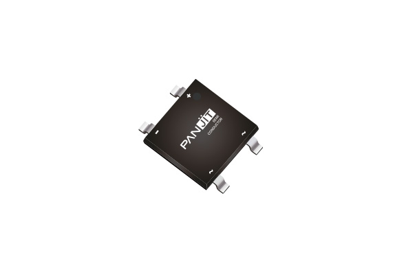
PMS310 diode is a cutting-edge electronic component engineered to meet the demands of PD chargers and power adapters. The glass passivated bridge delivers exceptional performance, excellent heat-dissipation ability while ensuring reliability and efficiency in various applications.

Designed for automatic assembly, the PMS310 diode enhances the efficiency of production processes, saving valuable time and resources. With its surface mount design, the PMS310 serves as an excellent substitute for traditional plug-in bridges, simplifying printed circuit board designs and conserving space. Additionally, its ultra-thin profile allows for space-saving utilization on PCBs, making it an ideal choice for space-constrained designs.

Environmental responsibility is at the core of this diode's design. It is lead-free and fully compliant with EU RoHS 2.0 standards, promoting sustainable and eco-friendly manufacturing practices. Additionally, it meets halogen-free requirements according to IEC 61249, further enhancing its environmental credentials.

Manufactured in IATF 16949 certified facilities, this diode ensures top-notch quality and adherence to rigorous industry standards. Trust in the PMS310 diode to elevate the efficiency and performance of your power functions.

  • Package

    M4

  • Voltage

    1000V

  • Current

    3A

  • IFSM

    110A

  • IR

    5uA

  • Features

    • Glass passivated chip junction
    • Ideally suited for automatic assembly
    • Save space on printed circuit boards
    • Ultra thin profile package for space constrained utilization
    • Lead free in compliance with EU RoHS 2.0
    • Halogen-free according to IEC 61249 standard

Download

  • 產品文宣
    • PANJIT_Bridge_M4_GBL-2 & GBU-2 & KBJ-2_Flyer
      File format pdf

Maximum Ratings and Thermal Characteristics (TA = 25°C unless otherwise noted)

PARAMETER SYMBOL LIMIT UNITS
Maximum Repetitive Peak Reverse Voltage VRRM 1000 V
Maximum RMS Voltage VRMS 700 V
Maximum DC Blocking Voltage VDC 1000 V
Maximum Average Forward Current IF(AV) 3 V
Peak Forward Surge Current : 8.3 ms Single Half Sine-Wave Superimposed on Rated Load @TA = 25°C IFSM 110 A
Peak Forward Surge Current : 8.3 ms Single Half Sine-Wave Superimposed on Rated Load @TA = 125°C IFSM 80 A
Peak Forward Surge Current : 1.0 ms Single Half Sine-Wave Superimposed on Rated Load @TA = 25°C IFSM 200 A
Peak Forward Surge Current : 1.0 ms Single Half Sine-Wave Superimposed on Rated Load @TA = 125°C IFSM 150 A
I2 t rating for fusing ( t = 8.3ms) I2 t 50.2 A2S
Typical Junction Capacitance Measured at 1 MHZ and Applied VR = 4 V CJ 40 pF
Typical Thermal Resistance RθJA
RθJL
RθJC
30
10
12
°C/W
Operating Junction and Storage Temperature Range TJ, TSTG -55~150 °C

Electrical Characteristics (TA = 25°C unless otherwise noted)

PARAMETER SYMBOL TEST CONDITION MIN. TYP. MAX. UNITS
Forward Voltage VF IF = 1.5A, TJ = 25°C - - 1.05 V
Reverse Current IR VR = 1000V, TJ = 25°C - - 5 μA
Reverse recovery time TRR VR = 1000V, TJ = 125°C - - 100 μA
新增詢問清單?

您確定您要新增此品項至詢問清單中?