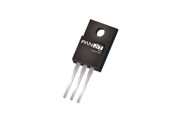
Absolute Maximum Ratings (TA = 25°C unless otherwise specified)
| PARAMETER | SYMBOL | LIMIT | UNITS | |
|---|---|---|---|---|
| Drain-Source Voltage | @ Tjmax - |
VDS VDS |
700 600 |
V |
| Gate-Source Voltage | VGS | ±30 | V | |
| Continuous Drain Current | TC=25°C TC=100°C |
ID | 35 22 |
A |
| Pulsed Drain Current | TC=25°C | IDM | 90 | A |
| Single Pulse Avalanche Energy | EAS | 738 | mJ | |
| MOSFET dv/dt ruggedness | dv/dt | 115 | V/ns | |
| Reverse Diode dv/dt | dv/dt | 100 | V/ns | |
| Maximum diode commutation speed | diF/dt | 1200 | A/µs | |
| Insulation Withstand Voltage for ITO-220AB-F | VISO | 3.5 | kV | |
| Power Dissipation | TC=25°C TC=100°C |
PD | 34 14 |
W |
| Operating Junction and Storage Temperature Range | TJ, TSTG | -55~150 | °C | |
| Thermal Characteristics | ||||
| PARAMETER | SYMBOL | MAXIMUM | UNITS | |
| Thermal Resistance | Junction-to-Case Junction-to-Ambient |
RθJC RθJA |
3.7 62.5 |
°C/W |
Electrical Characteristics (TA = 25°C unless otherwise specified)
| PARAMETER | SYMBOL | TEST CONDITION | MIN. | TYP. | MAX. | UNITS |
|---|---|---|---|---|---|---|
| Static | ||||||
| Drain-Source Breakdown Voltage | BVDSS | VGS=0 V, ID=10 mA | 600 | 710 | - | V |
| Gate Threshold Voltage | VGS(th) | VDS=VGS, ID=250 uA | 4.3 | 4.8 | 5.8 | V |
| Drain-Source On-State Resistance | RDS(on) | VGS=10 V, ID=19.5 A | - | 89 | 105 | mΩ |
| Zero Gate Voltae Drain Current | IDSS | VDS=600 V, VGS=0 V | - | - | 10 | uA |
| Gate-Source Leakage Current | IGSS | VGS=±30 V, VDS=0 V | - | - | ±100 | nA |
| Transfer characteristics | gfs | VDS=20 V, ID=19.5 A | - | 35 | - | S |
| Dynamic | ||||||
| Total Gate Charge Gate-Source Charge Gate-Drain Charge |
Qg Qgs Qgd |
VDS=480 V ID=19.5 A VGS=10 V |
- - - |
60 22 24 |
- - - |
nC |
| Input Capacitance Output Capacitance Reverse Transfer Capacitance |
Ciss Coss Crss |
VDS=400 V VGS=0 V f=250 kHZ |
- - - |
2995 70 20 |
- - - |
pF |
| Effective Output Capacitance Energy Related | Co(er) | VDS=0 V to 400 V, VGS=0 V,f=250 kHZ |
- | 116 | - | pF |
| Turn-On Delay Time Turn-On Rise Time Turn-Off Delay Time Turn-Off Fall Time |
td(on) tr td(off) tf |
VDD=300 V ID=19.5 A VGS=10 V RG=25 Ω |
- - - - |
108 95 175 49 |
- - - - |
ns |
| Gate Resistance | Rg | f=1.0 MHz | - | 11 | - | Ω |
| Drain-Source Diode | ||||||
| Diode Forward Voltage | VSD | IS=19.5 A VGS=0 V |
- | 0.95 | 1.5 | V |


