


Product Categories Overview
-
Power Management ICs
PANJIT provides Flyback controller/Active Bridge Controller IC to match different circuit structures and applications.
-

Signal Chain ICs
PANJIT provides competitive interface, sensor, and logic products for accurate and reliable monitoring, protection, and control.
-
Motor Control ICs
PANJIT simplifies designs, reduces board space and system costs, meeting the requirements of brushless DC motors in home appliances, water pumps, BLDC motors, etc.
-
MOSFETs
PANJIT provides Low/Medium/High voltage MOSFETs to match circuit structures. By combining our product design and experience, we can offer customized products.
-
IGBTs
PANJIT's IGBTs are committed to pursuing the highest standards in terms of performance and quality. They are designed with the latest Field Stop Trench gate technology to provide a comprehensive portfolio of discrete IGBTs, achieving the highest value for various applications.
-
Schottky Diodes
PANJIT's Schottky Rectifier has the characteristic of low forward voltage losses, which improves power efficiency, and low leakage current, which improves stability and reliability.
-
SiC Devices
SiC devices have low on-resistance, superior high-temperature, high-frequency, and high-voltage performance due to the characteristics of third-generation semiconductors.
-
Diode Rectifiers
PANJIT provides various types of rectifiers based on the recovery time: general purpose, fast recovery, ultra fast recovery, super fast recovery, hyper fast recovery, and FREDs.
- Small Signal Switching Diodes (VRRM = 50 - 350V)
- General Purpose Rectifiers (VRRM = 50 - 1700V)
- Fast Recovery Rectifiers (TRR = 150 - 500ns)
- Ultra Fast Recovery Rectifiers (TRR = 50 - 100ns)
- Super Fast Recovery Rectifiers (TRR = 25 - 50ns)
- Hyper Fast Recovery Rectifiers (TRR = 15 - 35ns)
- FRED (VRRM = 600 - 1200V, IF = 8 - 60A)
-
Protection Devices
PANJIT's protection devices are made using our self-designed wafer and self-packaging technology. We develop products that exhibit excellent transient responses.
-
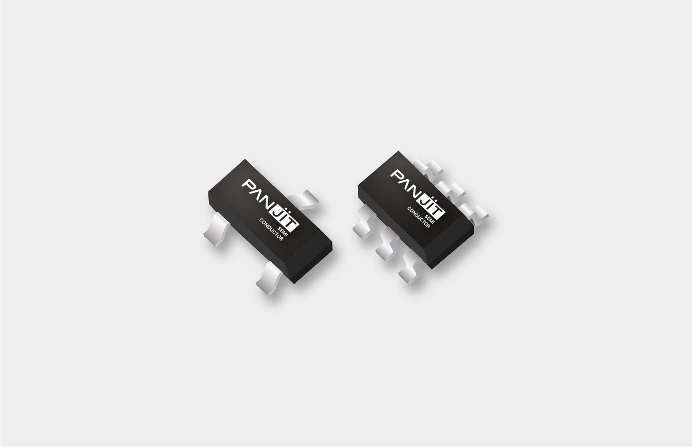
Bipolar Junction Transistors
A variety of transistor products are available, including general transistors, low collector-emitter saturation voltage transistors, and composite transistors (which combine transistors, diodes, and Zener diodes).
-
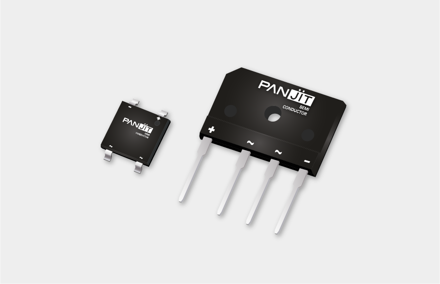
Bridges
Bridge Rectifiers (VRRM = 50 - 1000V) and Schottky Bridges (VRRM = 40 - 100V).
It is generally used as AC/DC rectification. -
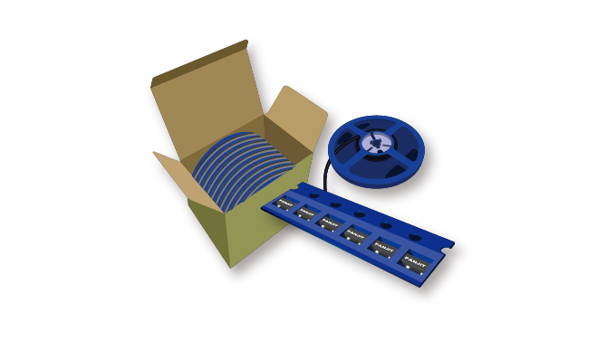
Packing information
PANJIT provides 3 different packing methods to carry our product, each method comes in different size of carton. Detail packing information as below: